PRODUCT
Tel:400-685-8582
Tel:+86-21-57715555
+86-21-37831986
Fax:+86-21-37831846
Phone:13817716438
Email:weho@chinaweho. com
Address:Building 2, No.8 Nanle Road, Songjiang District, Shanghai
TDGC2 (J) single-phase contact voltage regulator
- Category:TSGC TDGC Contact Regulator
- Scope of application TDGC(2), TSGC(2) series voltage regulators have the characteristics of beautiful appearance, undistorted waveform, small size, light weight, high efficiency, convenient use and reliable operation, and their performance is more
- Hotline:021-57715555 13817716438
Scope of application
TDGC(2), TSGC(2) series voltage regulators have the characteristics of beautiful appearance, undistorted waveform, small size, light weight, high efficiency, convenient use and reliable operation, and their performance is more superior. It can be widely used in industry (such as chemical industry, metallurgy, instrumentation, electromechanical manufacturing, light industry, etc.), scientific experiments, public equipment, and household appliances to achieve voltage regulation, temperature control, speed regulation, dimming and power control. , is an ideal AC voltage regulation power supply.
The main technical parameters
★The basic parameters of the regulator are specified in Table 1
★Rated (output) capacity of voltage regulator: Calculation formula: P=m12×U2×10(KVA)
In the formula: P-voltage regulator rated output capacity (KVA)
m-number of phases, single-phase m=1; three-phase m=3
I2-rated output current (A) U2 maximum output voltage (V) (three-phase line voltage)
★Insulation grade of the voltage regulator: The grade of the voltage regulator is A, and the average temperature rise limit of the coil is 60℃.
★Overload capacity, the voltage regulator is allowed to exceed the rated output current value for a short time, but cannot exceed the provisions of Table 2.
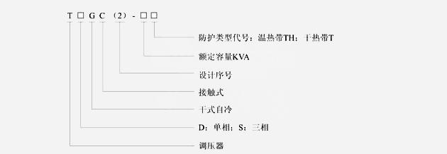
Models and what they mean

Main technical features
★Basic principle
The voltage regulator is an autotransformer with a continuously adjustable turns ratio. When the brush of the voltage regulator slides along the polished surface of the coil with the help of the handwheel spindle and the brush holder, the turns ratio can be continuously changed. This allows the output voltage to smoothly adjust from zero to maximum.
★Main structure
①Unit structure: The single-phase 0.2KVA 10KVA voltage regulator is a voltage regulator unit structure, a coil with a polished surface with a certain width on the upper end surface is fixed on the base of the project, and the brushes of the contact group are connected with the spring pressure under the spring pressure. The polished surface of the coil is in close contact. Turn the handwheel to drive the brush to slide on the polished surface of the coil to adjust the pressure. The unit voltage regulator is generally a desktop with a protective ventilation cover outside.
②Single-phase assembly structure: The single-phase large-capacity voltage regulator is assembled from several units of the same specification. The brushes of each unit are assembled on the same spindle, the coil input ends are connected in parallel, and the output end is connected to a balanced reactor , to balance the current distribution between cells and suppress circulating currents.
③ Three-phase assembly structure: The three-phase voltage regulator is assembled coaxially by three units of the same specification.
④Brush structure: 3KVA and below unit voltage regulators use 1 to 2 graphite brushes and a metal frame with good heat dissipation, 4KVA and above unit voltage regulators use two copper-graphite composite brushes, brush contact group The pressure plate of the coil is fixed on the upper end of the coil to limit its axial position, and is locked with the main shaft by screws. carried out.
Conditions of Use
★Ambient temperature: the highest temperature is +40℃, the lowest temperature is -5℃;
★Altitude: The altitude of the installation site of the voltage regulator should not exceed 1000 meters;
★Relative air humidity: The average relative humidity of the wettest month is 90%, and the average temperature of the month is 25℃
★Power supply voltage waveform: The power supply voltage waveform is sine wave or similar to sine wave;
★The installation site has no gas, vapor, chemical deposition, dust, dirt and other explosive and corrosive media that seriously affect the insulation of the regulator;
★The installation site should be free from severe vibration and turbulence;
★Indoor use;
★Do not use in parallel
Installation, use and maintenance
★For the newly installed or long-term unused voltage regulator, the insulation resistance of the coil to the ground must be measured with a 500-volt megohmmeter before operation, and the value of the voltage regulator can be safely used when the value is not less than 5 megohms, otherwise it should be heat-baked. The heat-drying treatment method can generally be charged drying or sent to a drying room for drying. After drying, check whether the fasteners are loose, and tighten them if they are loose.
★The power supply voltage should conform to the input voltage on the nameplate of the voltage regulator.
★The voltage regulator must be well grounded to ensure safety.
★When using, always pay attention that the output current does not exceed the rated value. If there is a short-time load, it cannot exceed the regulations in Table 2, otherwise the life of the voltage regulator will be reduced or even burned.
★When using, the handle should be rotated slowly and evenly to avoid damage to the brush or sparks.
The use of the voltage regulator should be checked frequently. If the brushes are found to be too worn or damaged, the brushes of the same specification should be replaced in time, and the bottom surface of the brushes should be ground by turning the handwheel several times under the brushes with a zero-addition sandpaper pad. It can be used only when it is flat and has good contact. The exchanged copper-graphite composite brushes must strictly meet the standardization requirements.
★The surface accepted by the coil and brush should always be kept clean, otherwise it is easy to cause sparks and burn out the surface of the coil. If it is found that there are black spots on the surface of the coil, it can be wiped with cotton yarn dipped in alcohol (90%) until the surface spots are removed.
★From the power supply to the voltage regulator, the wires and wire terminal connectors from the voltage regulator to the load should be in good contact and can pass the rated current of the voltage regulator.
★Do not use the hand wheel when handling the regulator, but use the handle or lift the whole product to move.
★The regulator needs to be installed horizontally on the panel, (only for unit regulator structure) or installed vertically on other bases, it can be fixed using the mounting holes of the regulator base. ★The regulator should always be kept clean. No water droplets, oil stains, etc. will fall into the regulator. The regulator should be powered off regularly to remove the dust accumulated inside.
| model |
Rated capacity (KVA) |
Phase |
Rated frequency (Hz) |
Rated input voltage (V) |
Output voltage range (V) |
Rated output current (A) |
| TDGC2-0.2 | 0.2 | 1 | 50 | 220 | 0~250 | 0.8 |
| TDGC2-0.5 | 0.5 | 1 | 50 | 220 | 0~250 | 2 |
| TDGC2-1 | 1 | 1 | 50 | 220 | 0~250 | 4 |
| TDGC2-2 | 2 | 1 | 50 | 220 | 0~250 | 8 |
| TDGC2-3 | 3 | 1 | 50 | 220 | 0~250 | 12 |
| TDGC2-5 | 5 | 1 | 50 | 220 | 0~250 | 20 |
| TDGC2-7 | 7 | 1 | 50 | 220 | 0~250 | 28 |
| TDGC2-10 | 10 | 1 | 50 | 220 | 0~250 | 40 |
| TDGC2-15 | 15 | 1 | 50 | 220 | 0~250 | 60 |
| TDGC2-20 | 20 | 1 | 50 | 220 | 0~250 | 80 |
| TDGC2-30 | 30 | 1 | 50 | 220 | 0~250 | 120 |
| TSGC2-3 | 3 | 3 | 50 | 380 | 0~430 | 4 |
| TSGC2-6 | 6 | 3 | 50 | 380 | 0~430 | 8 |
| TSGC2-9 | 9 | 3 | 50 | 380 | 0~430 | 12 |
| TSGC2-12 | 12 | 3 | 50 | 380 | 0~430 | 16 |
| TSGC2-15 | 15 | 3 | 50 | 380 | 0~430 | 20 |
| TSGC2-20 | 20 | 3 | 50 | 380 | 0~430 | 27 |
| TSGC2-30 | 30 | 3 | 50 | 380 | 0~430 | 40 |
Table 1

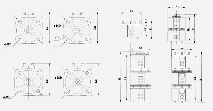
Table 2. Appearance, installation dimensions and weight table
| model | Outline and installation dimensions (mm) | Weight Kg | Outline | ||||||||
| L2 | L1 | H | H1 | h | φ | d | D | R | |||
| TDGC2-0.2 | 130 | 115 | 125 | 90 | twenty three | 100 | 4 | 8 | 172.5 | 2.4 | Figure 5 |
| TDGC2-0.5 | 150 | 132 | 136 | 98 | twenty three | 116 | 4 | 8 | 172.5 | 3.3 | Figure 5 |
| TDGC2-1 | 207 | 182 | 158 | 120 | 30 | 156 | 5 | 12 | 172.5 | 6.1 | Figure 5 |
| TDGC2-2 | 207 | 182 | 190 | 140 | 30 | 156 | 5 | 12 | 92 | 8.5 | Figure 5 |
| TDGC2-3 | 235 | 210 | 198 | 140 | 36 | 190 | 6 | 12 | 92 | 11 | Figure 5 |
| TDGC2-5 | 272 | 245 | 248 | 182 | 36 | 218 | 8 | 16 | 112 | 15.5 | Figure 5 |
| TDGC2-7 | 350 | 320 | 262 | 192 | 36 | 290 | 8 | 16 | 131 | 26.5 | Figure 5 |
| TDGC2-10 | 350 | 320 | 262 | 192 | 36 | 290 | 8 | 16 | 131 | Figure 5 | |
| TDGC2-15 | 395 | 320 | 505 | 420 | 36 | 10 | 16 | 172.5 | 28.8 | Image 6 | |
| TDGC2-20 | 395 | 320 | 505 | 420 | 36 | 10 | 16 | 172.5 | 53 | Figure 7 | |
| TDGC2-30 | 395 | 320 | 730 | 645 | 36 | 10 | 16 | 59 | Figure 8 | ||
| TSGC2-3 | 207 | 182 | 450 | 396 | 30 | 8 | 12 | 88.5 | Figure 8 | ||
| TSGC2-6 | 207 | 182 | 557 | 490 | 30 | 8 | 12 | Figure 8 | |||
| TSGC2-9 | 235 | 210 | 567 | 490 | 36 | 8 | 12 | Figure 8 | |||
| TSGC2-12 | 272 | 245 | 681 | 616 | 36 | 10 | 16 | Figure 8 | |||
| TSGC2-15 | 272 | 245 | 681 | 616 | 36 | 10 | 16 | Figure 8 | |||
| TSGC2-20 | 350 | 320 | 730 | 645 | 36 | 10 | 16 | Figure 8 | |||
| TSGC2-30 | 350 | 320 | 730 | 645 | 36 | 10 | 16 | Figure 8 | |||


 TSGC TDGC Contact Regulator

